Centrifugal fans serve as the backbone of modern industrial ventilation, heating, cooling, and air filtration systems. As the primary method for moving air in environments ranging from commercial kitchens to heavy manufacturing plants, their efficiency dictates not only operational costs but also the carbon footprint of the facility. Understanding how these machines convert mechanical energy into kinetic energy and pressure rise is critical for engineers and facility managers who seek to optimize system performance.
Understanding the Aerodynamic Principles of Centrifugal Fans
The fundamental operation of a centrifugal fan relies on the conversion of rotational energy into air velocity and pressure. When the impeller rotates, air enters the center of the fan, is pushed outward by centrifugal force, and then channeled through a housing that directs the airflow toward the discharge. Efficiency in this context is defined as the ratio of the power delivered to the airstream to the power input at the shaft.
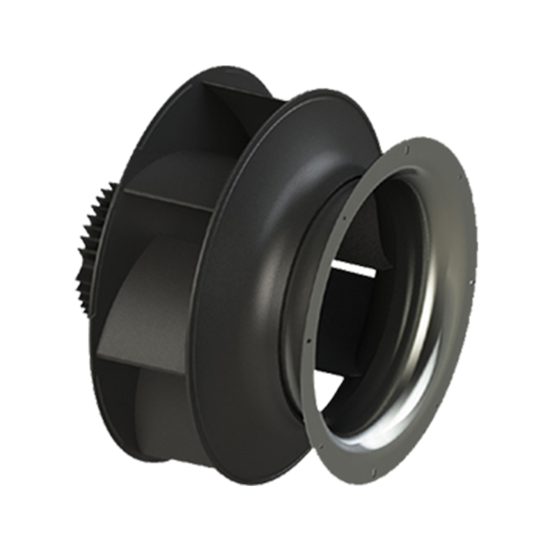
The impeller design remains the most significant variable in determining how effectively energy is utilized. Forward-curved, backward-inclined, and airfoil impellers each possess distinct efficiency profiles. Airfoil blades, for instance, are designed with aerodynamic shapes that minimize turbulence and separation as the air leaves the blade tip. This reduction in wake formation results in a smoother flow pattern within the fan housing, which contributes to higher static efficiency compared to flat-blade alternatives. The internal flow path, often referred to as the scroll or volute, must also be precision-engineered to minimize friction losses as the air decelerates and builds pressure.
Factors Influencing Operational Efficiency
Efficiency is rarely static; it fluctuates based on the operating point of the fan on its performance curve. Every fan is designed to operate at an Optimal Efficiency Point (OEP). When a system requires a fan to operate significantly to the left or right of this point, energy losses occur due to stalling, excessive turbulence, or mechanical drag.
One primary factor influencing this performance is the clearance between the impeller inlet and the inlet bell. Tight tolerances here prevent recirculating air from leaking back into the suction side, a phenomenon known as backflow. When this gap is excessive, the fan consumes more power for the same volume of air delivered, significantly degrading the system efficiency. Furthermore, the smoothness of the interior surfaces of the fan housing plays a role. Any irregularities in casting or welding can disrupt the boundary layer of the airflow, creating localized pockets of turbulence that manifest as increased drag and power consumption. Proper maintenance of the inlet conditions is just as critical as the fan design itself, as uneven or swirling air entering the fan reduces its ability to impart kinetic energy effectively.
Comparative Efficiency of Centrifugal Extractor Fan Systems
A centrifugal extractor fan is frequently utilized in commercial and industrial settings for the removal of particulate matter, steam, and hazardous fumes. Because these systems often require high pressure to overcome the resistance of filters, ductwork, and hoods, efficiency becomes a complex equation involving both fluid dynamics and static pressure requirements.
In a typical extraction application, the system resistance curve often intersects the fan curve in a way that necessitates high-speed operation. Unlike high-volume low-pressure supply fans, extractor units must maintain flow against high impedance. High-efficiency centrifugal extractor fan models mitigate losses by using variable speed drives to match the motor output to the immediate extraction needs. By reducing the rotational speed during periods of low demand, these systems avoid the high energy penalties associated with throttling the airflow through dampers. Throttling is notoriously inefficient because it adds artificial resistance to the system, causing the fan to operate at a higher pressure than necessary and wasting energy through sheer friction.
Impeller Geometry and Performance Dynamics
The shape and angle of the impeller blades define the power characteristic of the centrifugal fan. Backward-curved impellers are widely regarded as the most efficient choice for high-pressure, variable-flow applications. They possess a self-limiting power characteristic, which means that the motor is less likely to become overloaded if the system pressure drops suddenly. This inherent safety feature is complemented by high hydraulic efficiency, as the backward slope of the blades allows the air to leave the impeller at a lower relative velocity, reducing the energy loss during the transition into the volute.
Conversely, forward-curved impellers are often chosen for lower-pressure applications where space is at a premium. While they are smaller and move more air relative to their size, their efficiency curve is typically narrower. They are prone to instability if operated incorrectly, as the energy conversion process involves higher blade-tip speeds to achieve the same pressure rise. Understanding the relationship between blade geometry and load is essential for selecting a fan that will maintain high efficiency over the lifecycle of the system rather than just during initial commissioning.
Managing System Losses and Aerodynamic Efficiency
Energy loss in centrifugal fan systems is generally categorized into three types: mechanical, leakage, and aerodynamic. Mechanical losses occur in bearings, belts, and motor inefficiencies. While these are often external to the fan design, they must be considered when calculating total system efficiency. Leakage losses are primarily related to the gap between the rotating impeller and the stationary inlet cone. Even a small leakage path can lead to a significant drop in the pressure head, forcing the motor to work harder to compensate.
Aerodynamic losses, however, represent the largest opportunity for improvement. These are caused by the separation of the airflow from the blade surface, resulting in eddies and vortices that consume energy without contributing to the movement of air. Engineers combat these losses by implementing guide vanes at the inlet, which straighten the incoming air, ensuring it strikes the impeller blades at the correct angle of attack. By ensuring laminar flow characteristics at the entry, the fan can maintain a stable pressure coefficient even when the air volume requirements fluctuate.
Best Practices for Maintaining High Performance
Operating a centrifugal fan at its peak requires consistent attention to the physical condition of the hardware. Over time, the accumulation of dust or debris on the blades alters the aerodynamic profile of the impeller. Even a thin layer of particulate matter can disrupt the airflow, creating turbulence and reducing the lift generated by the blades. Regular cleaning cycles are therefore an essential component of maintaining high fan efficiency.
In addition to cleanliness, the integrity of the duct connections must be verified. Leaks in the suction ductwork introduce extra air that the fan must process, while leaks in the discharge ductwork mean that the work performed by the fan is not reaching the intended destination. Both scenarios result in a mismatch between the electrical energy consumed and the useful work performed. Periodic inspections of the fan housing, bearing lubrication, and drive belt tension ensure that the mechanical components are not adding unnecessary drag to the system. When these factors are addressed, the centrifugal fan operates closer to its theoretical efficiency limit, minimizing the strain on the motor and extending the service life of the equipment.



 English
 中文简体
中文简体 русский
 Español




 OEM/ODM HVAC Axial Fan Manufacturers
