English
 中文简体
中文简体 русский
 Español
News
Home / News / Industry News / Axial Fan vs Centrifugal Fan: Complete Electronics Cooling Selection Guide
An Axial fan moves large volumes of air along its rotational axis at low static pressure and is the right choice for open, unobstructed cooling paths. A Centrifugal fan, also called a Blower fan, redirects air at a 90 degree angle and builds high Static pressure, making it the correct choice whenever airflow must push through dense components, narrow ducts, or tightly restricted enclosures. For Electronics cooling and Thermal management decisions, the single most useful rule is this: if your system has low System impedance and needs maximum Airflow rate in CFM (Cubic Feet per Minute), use an Axial fan; if your system has high System impedance from filters, heatsinks, or constrained channels, use a Centrifugal fan or Blower fan. Everything else in Fan selection is a refinement of that core principle.
| Criterion | Axial fan | Centrifugal fan |
|---|---|---|
| Airflow direction | Parallel to shaft axis | Perpendicular, exits at 90 degrees |
| Static pressure capability | Low, typically 0.05 to 0.5 inches H2O | High, typically 0.5 to 5 inches H2O or more |
| Airflow rate in CFM (Cubic Feet per Minute) | High for a given frame size | Moderate, traded for pressure |
| Profile and mounting | Thin, inline, mounts on flat panel | Taller, side discharge, suits narrow enclosures |
| Noise level | Lower at equivalent airflow | Higher due to blade tip and scroll turbulence |
| Best application | Open enclosures, case fans, rack ventilation | Laptops, projectors, medical devices, server blowers |
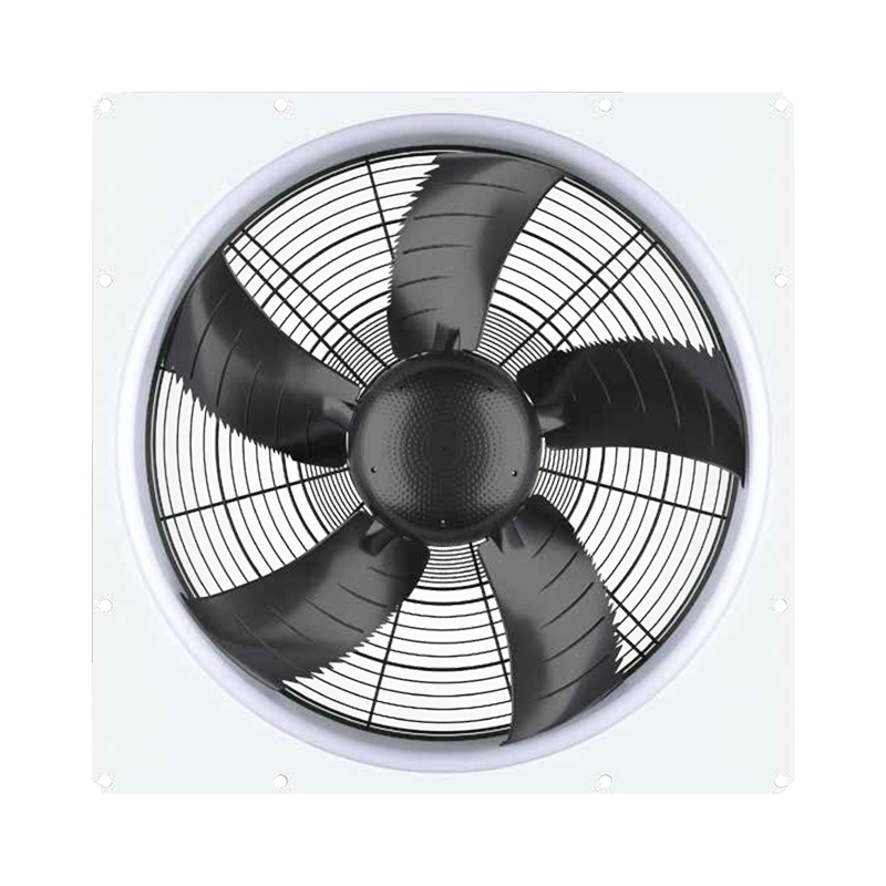
An Axial fan works by rotating a set of angled blades around a central hub. As the blades spin, they act on air the same way a propeller acts on air or water, pushing fluid in the direction the shaft points. This defines the Airflow direction of axial fans: air enters the fan face axially, meaning straight into the spinning blades, and exits in the same axial direction on the other side. There is no change in flow direction, which is why Axial fan installations are simple to integrate and why they dominate anywhere a straight through airflow path is available.
The blade geometry of an Axial fan is the primary determinant of its performance. A higher blade pitch angle moves more air per revolution but also increases the load on the motor and the turbulence behind the blade, which raises noise. Most commercial Axial fan products for Electronics cooling use a blade pitch optimized for the best balance of Airflow rate in CFM (Cubic Feet per Minute) and acoustic output at a given rotational speed, which is why the datasheet always shows both airflow and noise figures together rather than either one in isolation.
What is an advantage of using an axial fan? The primary advantages are a high Airflow rate relative to the fan's physical frame size, a thin axial profile that fits between panels, and a significantly lower cost than a comparable Centrifugal fan at the same diameter. A 120 mm Axial fan running at 2000 RPM typically delivers 60 to 110 CFM (Cubic Feet per Minute) while consuming only 3 to 7 watts, making it extremely energy efficient for the volume of air moved. A second important advantage is that multiple Axial fan units can be stacked in series or arrayed in parallel across a panel to scale airflow or pressure without needing a larger, more expensive Centrifugal fan assembly.
The limitation of the Axial fan is precisely its low Static pressure capability. As System impedance rises, meaning as the airflow path becomes more obstructed, the Axial fan's delivered CFM (Cubic Feet per Minute) drops steeply. This is visible on any fan curve for an Axial fan: the curve descends sharply as back pressure increases, and the fan reaches its stall pressure at a relatively low value compared to a Centrifugal fan of the same diameter.
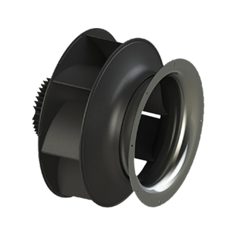
How does a centrifugal fan work? A Centrifugal fan, also marketed as a Blower fan in many electronics product lines, draws air in axially through an inlet at the center of its impeller and then accelerates that air radially outward using centrifugal force as the impeller spins. The air is flung to the outer rim of the scroll or volute housing, where kinetic energy is converted into pressure, and then the air exits through a single discharge port oriented at 90 degrees to the inlet. This fundamental change in flow direction is what gives the Centrifugal fan its defining advantage: it can generate far higher Static pressure than an Axial fan of the same diameter because the scroll housing captures the radial velocity of the air and converts it into usable pressure head.
Are centrifugal fans more powerful? In terms of pressure generation, yes. High static pressure centrifugal blowers can generate 5 to 10 times the maximum Static pressure of a comparably sized Axial fan, which is why they are specified whenever airflow must push through a heat exchanger core, a dense filter, a closely packed PCB array, or a long narrow duct where System impedance is high. The trade off is that a Centrifugal fan is physically taller than an Axial fan of the same inlet diameter, consumes more power at equivalent airflow against resistance, and typically produces a more tonal noise profile due to the interaction of blades passing the fixed discharge cutoff point in the scroll housing.
Centrifugal fan impeller blade shapes vary significantly and each shape produces a different balance of pressure, flow, and efficiency. Backward curved blades are the most efficient shape and are standard in high performance Electronics cooling blowers because they are non overloading, meaning motor power consumption does not spike if the system resistance drops unexpectedly. Forward curved blades move more air at low pressure and are common in HVAC and consumer appliance blowers. Backward inclined flat blades offer a middle ground and are easier to manufacture, making them cost effective for mid range applications.
| Blade Type | Pressure Capability | Efficiency | Common Application |
|---|---|---|---|
| Backward curved | High | Highest, non overloading | Server blowers, medical devices, precision instruments |
| Forward curved | Low to moderate | Moderate | HVAC, consumer appliances, low noise environments |
| Backward inclined flat | Moderate | Good | Industrial ventilation, mid range electronics |
| Radial flat | Very high | Lower | Material handling, dirty air applications |
Effective Fan selection requires a clear understanding of four interdependent quantities: Static pressure, Airflow rate, CFM (Cubic Feet per Minute), and System impedance. Confusing these or treating them in isolation is the root cause of most cooling failures in electronic product development.
Static pressure is the force per unit area that a fan exerts on the air it moves, measured in inches of water column (in H2O) or Pascals (Pa). When a fan pushes air through a restricted path, it must overcome the resistance of that path, and Static pressure is the currency it uses to do so. A fan that generates 0.1 inches H2O of maximum Static pressure will deliver close to zero airflow if the system it feeds requires 0.15 inches H2O to overcome its resistance.
Airflow rate is the volume of air moved per unit of time. In North American engineering and most electronics datasheets, this is expressed as CFM (Cubic Feet per Minute), while metric datasheets use cubic meters per hour (m3/h) or liters per second (L/s). A standard 80 mm Axial fan running at 2500 RPM typically delivers 25 to 40 CFM (Cubic Feet per Minute) in free air but may deliver only 10 to 15 CFM (Cubic Feet per Minute) when installed inside a computer case with moderate System impedance. This gap between free air performance and installed performance is where many Thermal management mistakes originate.
System impedance, sometimes called system resistance, is the total pressure drop across all components in the airflow path at a given flow rate. Every element in the path, grilles, filters, heatsinks, PCB card gaps, cable bundles, adds to System impedance. As airflow rate increases, System impedance rises roughly with the square of flow velocity, which is why system resistance curves on a fan curve chart appear as parabolic lines rather than straight ones. The operating point of any fan in any real enclosure is the intersection of the fan's pressure versus flow curve with the system's resistance curve.
Understanding fan curves airflow vs static pressure is the most practically valuable skill in Thermal management and Fan selection work. A fan curve is a two axis chart where the horizontal axis shows Airflow rate in CFM (Cubic Feet per Minute) and the vertical axis shows Static pressure. Every fan has a characteristic curve that starts at maximum Static pressure when flow is zero, curves downward as flow increases, and ends at maximum free air flow when Static pressure is zero.
The system resistance curve is overlaid on the same chart. It starts at the origin (zero flow, zero pressure) and curves upward as flow increases. The point where the two curves cross is the operating point: the actual Airflow rate and Static pressure at which the fan will run in that specific installation. Moving that operating point is the central task of Fan selection and Thermal design.
For an Axial fan, the fan curve drops steeply as back pressure rises. This means an Axial fan operating near its stall pressure point delivers very little actual CFM (Cubic Feet per Minute) even though it is spinning at full speed and consuming full power. For a Centrifugal fan, the pressure curve is flatter across a wider range of flow rates, meaning the Centrifugal fan maintains useful airflow even as System impedance increases. This difference in curve shape is the core practical reason to choose a Centrifugal fan for restricted space designs: not just because it generates more maximum Static pressure, but because it maintains that pressure across a broader range of operating conditions.
Most fan datasheets also include a power curve and sometimes a noise curve on the same chart. Reading all three together gives a complete picture of what the fan will actually deliver at the specific System impedance point of the target application, rather than the optimistic free air figures that appear in marketing summaries. Thermal engineers who skip this step and size fans purely from the free air CFM (Cubic Feet per Minute) number consistently find that their builds run hotter than predicted once assembled, because installed airflow is always lower than free air airflow.
The Difference between axial and centrifugal fans extends well beyond airflow direction and pressure capability. Understanding the full set of differences allows a Thermal management engineer or product designer to make a confident Fan selection decision without defaulting to whichever fan type they used on the previous project.
| Attribute | Axial fan | Centrifugal fan |
|---|---|---|
| Airflow direction | Axial, inlet and outlet in line | Radial, outlet 90 degrees to inlet |
| Max Static pressure | 0.05 to 0.5 inches H2O typical | 0.5 to 5 inches H2O typical |
| Free air CFM (Cubic Feet per Minute) | High for frame size | Lower, pressure prioritized |
| Physical height | Thin, equals blade depth | Taller, includes scroll housing |
| Footprint | Square, matches panel cutout | Asymmetric, discharge extends to one side |
| Sensitivity to back pressure | High, airflow drops sharply | Low, maintains flow across wider range |
| Noise character | Broadband, generally lower dBA | Tonal blade pass frequency, higher dBA |
| Unit cost | Lower | Higher |
One often overlooked aspect of the Difference between axial and centrifugal fans is behavior when the system resistance changes during operation. A server with a clogged air filter presents higher System impedance to its fans than a clean server. An Axial fan in this situation loses airflow rapidly and the processor temperature climbs, potentially triggering thermal throttling or shutdown. A Centrifugal fan in the same situation maintains more of its airflow against the increased resistance, giving the system more thermal headroom before a fault condition is reached. This robustness to varying System impedance is a key reason why server and storage OEMs often prefer Centrifugal fan modules in high density deployments.
The decision between Axial fan vs centrifugal blower for electronics cooling comes down to four practical questions that can be answered quickly during the early design phase before any thermal simulation or prototype testing begins.
For a desktop computer case with large mesh panels, multiple 120 mm or 140 mm Axial fan units on front intake and rear exhaust are almost universally the correct answer. For a 1U rack server with dense PCB card arrays and a thin profile that constrains fan diameter, a pair of high speed Centrifugal fan modules in a push or pull arrangement is the correct solution. For a laptop with a very thin copper vapor chamber and fine pitch heatsink fins, a single Blower fan drawing air from below the keyboard and discharging out the rear edge is the only configuration that physically fits the thermal and geometric requirements simultaneously.
Noise level comparison axial vs centrifugal fans requires distinguishing between two different scenarios: free air open systems and installed restricted systems. In a free air open system, the Axial fan almost always wins on acoustics because it moves a large volume of air at low RPM, and noise scales strongly with rotational speed and blade tip velocity. A 120 mm Axial fan delivering 60 CFM (Cubic Feet per Minute) in an open case typically produces 25 to 35 dBA, which is considered quiet in most consumer and office environments.
In an installed system with significant System impedance, the Noise level comparison axial vs centrifugal fans reverses. The Axial fan, forced to fight against back pressure, accelerates to maximum RPM to maintain any useful airflow and generates considerable broadband noise from blade stall and turbulence. The Centrifugal fan, doing the same job against the same resistance with its characteristically flat pressure curve, runs at a lower fraction of its maximum speed and produces less total acoustic power even though its noise per RPM is higher than the Axial fan. In a restricted system, a properly selected Centrifugal fan running at 60 to 70 percent of maximum speed can deliver the same cooling CFM (Cubic Feet per Minute) as an Axial fan running at 95 percent of maximum speed, with a meaningful acoustic advantage in most measurements.
The tonal noise character of a Centrifugal fan is worth separate attention in any acoustically sensitive application. The blade pass frequency, the tone produced every time an impeller blade passes the fixed discharge cutoff in the scroll, is perceived by most listeners as more annoying than the broadband hiss of an Axial fan at the same total dBA level. Thermal management engineers in consumer electronics, medical devices, and home office products often prefer the Axial fan for precisely this reason even in moderately restricted systems, accepting a slightly higher RPM in exchange for noise that is less perceptible to end users.
High airflow low pressure cooling fans are the natural domain of the Axial fan, and specifying anything else in this scenario means paying more for less performance. Applications that genuinely feature low System impedance and need the maximum possible CFM (Cubic Feet per Minute) from the available panel space include open tower desktop computer cases, telecommunication outdoor cabinets with large louvered doors, industrial control panel cooling where the enclosure is deep and well vented, and data center row level cooling units where air travels through large open spaces between server racks.
For these High airflow low pressure cooling fans applications, a 120 mm or 140 mm Axial fan at 1200 to 1800 RPM delivers the best combination of airflow, noise, power consumption, and cost available. Stacking two Axial fan units in series in the same duct roughly doubles Static pressure with only a modest airflow penalty, which is useful when an otherwise open system has a single bottleneck such as a dense heatsink fin stack that the fans must push air through before the rest of the path opens up again.
High static pressure centrifugal blowers occupy a specific performance zone that Axial fan units genuinely cannot reach regardless of how many are arrayed in series. When System impedance exceeds roughly 0.5 to 0.8 inches H2O across the entire cooling path, High static pressure centrifugal blowers are the only single fan solution that delivers adequate airflow. This threshold is commonly crossed in the following product categories.
Choosing the Best cooling fan for high density server racks requires balancing Static pressure, Airflow rate in CFM (Cubic Feet per Minute), physical constraints, redundancy, and serviceability in ways that desktop or workstation Thermal management does not demand. High density server racks typically dissipate 20 to 40 kW or more per rack, which means airflow requirements are measured in hundreds of CFM (Cubic Feet per Minute) per 1U or 2U server, and the fans driving that airflow are among the highest stressed components in the entire data center.
For 1U rack servers, the dominant solution in the industry is an array of 4 to 7 dual rotor Centrifugal fan modules arranged across the rear of the server chassis, each module independently controlled and hot swappable for N plus 1 redundancy. These modules use backward curved impellers spinning at 15,000 to 25,000 RPM and deliver 15 to 30 CFM (Cubic Feet per Minute) each against the 0.8 to 2.0 inches H2O of System impedance that a densely loaded 1U server presents. An Axial fan at this diameter and speed would stall completely against this level of back pressure and deliver essentially no airflow.
For 2U and larger servers with more available fan diameter, larger Axial fan units in the 60 to 80 mm range become practical in some architectures, particularly when the server uses an open midplane design where airflow travels through large card cage openings with relatively low System impedance. However, even in these cases, the leading hyperscale server manufacturers have shifted toward Centrifugal fan modules in most product lines because of their superior performance stability across the full range of filter loading and thermal conditions encountered in real data center operation.
Best cooling fan for high density server racks summary by server form factor:
| Server Form Factor | Typical Power Density | Recommended Fan Type | Typical System impedance |
|---|---|---|---|
| 1U rack server | 200 to 500 W per unit | Centrifugal fan modules, N plus 1 array | 0.8 to 2.0 inches H2O |
| 2U rack server | 300 to 800 W per unit | Centrifugal fan modules or large Axial fan | 0.4 to 1.2 inches H2O |
| 4U tower or storage | 200 to 600 W per unit | Axial fan array with ducting | 0.1 to 0.5 inches H2O |
Selecting centrifugal fan for restricted space designs is a process that differs meaningfully from general fan selection, because the physical constraints of the enclosure often override pure aerodynamic preferences and require the engineer to optimize within a tightly bounded solution space.
The first parameter to establish when Selecting centrifugal fan for restricted space designs is the maximum available inlet diameter, since the impeller diameter is the single largest determinant of both pressure and flow capability. Even a few millimeters of additional inlet diameter significantly changes what a Centrifugal fan can deliver. For a laptop with 8 mm of available fan height, the choice may be limited to a 50 to 65 mm diameter impeller, and the entire thermal design must be built around what that size fan can actually achieve.
The second parameter is discharge direction and port size, since a Centrifugal fan's discharge must align with the enclosure's exhaust port. Most thin notebook Centrifugal fan designs discharge through a narrow slot along one edge of the enclosure, and the scroll housing geometry must route the discharge precisely to that slot without unnecessary bends that would add resistance and reduce delivered airflow.
A Thermal design guide for computer case cooling needs to address fan type selection, airflow path design, and the interaction between them as an integrated system rather than treating the fan as an isolated component decision. A powerful fan in a poorly designed airflow path will deliver disappointing results, while a modest fan in a well designed path can exceed the thermal performance of a more powerful fan fighting a chaotic or recirculating airflow.
A full tower or mid tower ATX case with mesh front panel, open card slots, and a rear exhaust opening has low System impedance across the main airflow path. Two or three 120 mm or 140 mm Axial fan units at the front drawing cool air in, combined with one or two Axial fan units at the rear and top exhausting hot air out, creates a positive front to rear pressure gradient that sweeps heat away from the CPU and GPU efficiently. This Thermal management approach works because the System impedance is low enough for Axial fan units to operate near their peak efficiency point on their fan curves.
A small form factor case with constrained internal volume, minimal panel openings, and a GPU with a reference style Blower fan cooler presents a very different System impedance picture. Here the GPU's own Blower fan, a Centrifugal fan that draws air in from above the PCB and exhausts directly out the rear bracket slot, is often a better thermal solution than an open air GPU cooler because it removes heat from the case immediately rather than recirculating it into the enclosed volume where it reduces CPU cooling effectiveness.
The Thermal design guide for computer case cooling principle that bridges all form factors: design the airflow path first, then select fans whose fan curves intersect the system resistance curve at the required CFM (Cubic Feet per Minute) and at a point well away from the stall region. A fan operating near stall is loud, inefficient, and delivers poor actual cooling despite high power consumption. A fan operating at 50 to 70 percent of its maximum flow rate is quiet, efficient, and has margin to increase speed if temperatures rise under load.
When to use a blower instead of an axial fan is ultimately a question answered by the combination of System impedance and physical geometry, and following the logic below prevents both over engineering and under engineering in any Thermal management project.
Use a Blower fan or Centrifugal fan when any of the following conditions applies:
Use an Axial fan when any of the following conditions applies:
The answer to when to use a blower instead of an axial fan is always rooted in System impedance: measure or estimate the resistance of the airflow path, plot it on the fan curve of each candidate, and the correct choice becomes obvious from where the operating point falls on each curve. No rule of thumb replaces this step in a serious Thermal management engineering process.
What is an advantage of using an axial fan? The primary advantages are a high Airflow rate in CFM (Cubic Feet per Minute) relative to the fan's physical frame size, a thin axial profile that fits directly on flat panels without a scroll housing, lower noise at equivalent airflow in open systems, lower unit cost, and wider availability in standard sizes from 25 mm up to 250 mm. These advantages make the Axial fan the dominant choice for any open, low System impedance cooling application.
Are centrifugal fans more powerful? In terms of Static pressure capability, yes by a large margin: High static pressure centrifugal blowers can produce 5 to 10 times the maximum Static pressure of a comparably sized Axial fan. In terms of free air Airflow rate in CFM (Cubic Feet per Minute), Axial fan units typically deliver more for a given frame diameter and power input. Which is more powerful depends entirely on what the application demands.
How does a centrifugal fan work? It draws air axially into the center of a spinning impeller and then flings that air radially outward using centrifugal force, converting kinetic energy into Static pressure inside a scroll housing before discharging it at 90 degrees to the inlet. An Axial fan moves air straight through in the same direction as the shaft rotates, generating Airflow rate in CFM (Cubic Feet per Minute) with minimal pressure conversion.
The Airflow direction of axial fans is parallel to the rotational shaft. Air enters the face of the spinning blades axially and exits from the opposite face in the same axial direction. This straight through flow path is the defining characteristic that makes the Axial fan simple to integrate into flat panel cutouts and inline duct sections.
Understanding fan curves airflow vs static pressure reveals the most important practical difference: the Axial fan's curve drops steeply as back pressure rises, meaning its delivered CFM (Cubic Feet per Minute) falls sharply with increasing System impedance. The Centrifugal fan's curve is much flatter, maintaining useful airflow across a wider range of back pressure. This curve shape difference, not the maximum pressure or maximum flow numbers alone, is what drives the Difference between axial and centrifugal fans in real installed applications.
The Best cooling fan for high density server racks in the 1U form factor is an array of backward curved Centrifugal fan modules running at 15,000 to 25,000 RPM, deployed in an N plus 1 hot swap arrangement. These deliver 15 to 30 CFM (Cubic Feet per Minute) each against the 0.8 to 2.0 inches H2O of System impedance typical in a densely loaded 1U server, a level of Static pressure that Axial fan units at comparable diameters cannot match.
When to use a blower instead of an axial fan: choose a Blower fan when System impedance exceeds approximately 0.5 inches H2O, when the enclosure is too thin for an Axial fan of adequate diameter, or when airflow must be redirected at 90 degrees to exit through a specific slot or port. Use an Axial fan when System impedance is low, maximum free air CFM (Cubic Feet per Minute) per unit of noise is the priority, and cost is a key constraint.
System impedance is the total resistance the airflow path presents to the fan. As System impedance rises, an Axial fan loses delivered CFM (Cubic Feet per Minute) rapidly because its fan curve is steep, while a Centrifugal fan maintains more airflow because its curve is flatter. Fan selection therefore starts with measuring or estimating System impedance and matching it to the correct fan type before any other parameter is considered.
In open low System impedance systems, the Noise level comparison axial vs centrifugal fans favors the Axial fan because it delivers large CFM (Cubic Feet per Minute) at low RPM and low dBA. In restricted high System impedance systems, the comparison reverses because the Axial fan must race to maximum RPM against back pressure while the Centrifugal fan covers the same thermal load at a lower fraction of its speed. The Centrifugal fan also has a tonal blade pass noise character that many listeners find more annoying than broadband Axial fan noise at the same total dBA level.
Selecting centrifugal fan for restricted space designs involves five core steps: first, measure the maximum available height and inlet diameter within the enclosure; second, estimate System impedance for the specific heatsink and duct path; third, confirm the discharge direction and port dimensions to ensure the scroll housing orientation fits the enclosure layout; fourth, check the fan curve at the calculated System impedance operating point to verify the delivered CFM (Cubic Feet per Minute) meets Thermal management requirements; and fifth, verify acoustic output at the operating speed against the product noise specification.
The variety of models, to meet the development needs of various regions in the world.

© 2025 Zhejiang Kemao Holding Group Co., Ltd.
All Rights Reserved.
 OEM/ODM HVAC Axial Fan Manufacturers